High efficiency concentrator

    First, the working principle of high efficiency concentrator
    d 2 (δ ρ ).g W(R 1 -R 2 )K
    From V 1 =---------- A=------------
    The 18μ and 86.4v 0 K 1 equations are known. Increasing the particle size of the solid particles in the slurry and the settling area of ​​the concentrator can increase the processing capacity of the concentrator. Adding a flocculating agent to the concentrator to agglomerate the fine particles into a mass can increase the particle size of the settled particles, and placing the inclined plate in the ordinary concentrator can increase the settlement area, shorten the sedimentation distance of the particles, and improve the concentration efficiency. The high-efficiency concentrator and the concentrated enthalpy of the inclined plate show its outstanding advantages from the above two aspects. Test and industrial production show that the high-efficiency thickener has a diameter of only two-thirds to one-half of the diameter of the ordinary thickener under the same processing capacity, and the floor space is about one-ninth of that of the ordinary thickener. Four points, and the processing capacity per unit area can be increased several times to several times.
    Second, the structure of high efficiency concentrator
    The structure of the trough body and the truss opacifier transmission unit of the highly efficient condensed song is substantially the same as that of the ordinary concentrator. The main reason for its high concentration efficiency is a special feed cylinder. There are three main types of high-efficiency concentrators commonly used abroad: Einco-BSP, Dorr-Oliver and Enviro-Cldar. The structure of the feed cylinder of the Amcor high-efficiency concentrator is shown in Figure 1. The cylinder is divided into three vertical mechanical mixing chambers and concentric with the central vertical axis of the thickener. The slurry is fed into the exhaust system, and the brought in air is discharged, and then enters the mixing chamber through the feeding pipe, and is fully mixed with the flocculating agent, and then directly fed to the grit layer through the feeding pipe which is radially distributed in the lower part of the mixing chamber. Upper part. After the liquid is filtered by the grit layer, it rises into an overflow, and the floc remains in the grit layer and enters the underflow.
    The structure of the Doll-Oliver high-efficiency concentrator is shown in Figure 2(a). The device has a special structure of the ore cylinder, as shown in Figure 2 (b). The slurry fed to the concentrator is divided into two strands, which are respectively fed to the upper and lower annular plates of the ore cylinder, and the flow direction of the two is reversed, so that the shearing force caused by the ore is minimized. When a certain concentration of flocculant is uniformly mixed with the slurry after being fed into the middle of the feeding cylinder, the formed floc flows smoothly from the region where the shearing force is the smallest to the concentration in the thickener.
    The structure of the Enviro type high-efficiency concentrator is shown in Figure 3. The center has a reverse cone-shaped reaction tube. The slurry flows up from the lower part of the circulation tube in the center of the reaction tube along the feeding tube, enters the reaction tube through the upper part of the circulation tube, is stirred by the rotating impeller, and is fully mixed with the flocculant. Then enter the grit layer from the bottom of the reaction tube. The solution passes through the upper portion of the grit layer and moves upward to form an overflow that enters the weir. The machine has a radial or peripheral overflow tank.
    Figure 1 Amcor high-efficiency concentrator structure
    1, 耙 transmission device; 2, mixer transmission device; 3, flocculant feed tube; 4, feeding cylinder; 5, 耙 arm;
    6, feed pipe; 7, overflow tank; 8, discharge pipe; 9, exhaust system
    Figure 2 Schematic diagram of Doyle-Oliver high-efficiency concentrator
    a, structural schematic; b, sectional view of the mine
    1. Transmission device; 2. Vertical shaft; 3. Feeding cylinder; 4. Overflow tank; 5. Tank body; 6. Bent arm; 7. Flocculation stirring tank;
    8, flocculation tank; 9, flocculation pump; 10, overflow tank; 11, overflow pump; 12, underflow pump; 13, concentration meter;
    14, dense phase interface sensor; 15, flocculant control system; 16, feed pipe [next]
    Third, the industrial application of high efficiency concentrator
    At present, the high-efficiency concentrator used abroad has a diameter of more than 40 meters. In the United States, Canada and Australia iron ore (concentrate and tailings), selected from the group of coal (mainly coal tailings), uranium (acid mine backflushing Yonghe), phosphate, plant residue and washed with SO 2 ferrous metals Widely used in industry. Its main industrial indicators are listed in the table below.
    Figure 3 Envero high efficiency concentrator
    1. Feeding pipe; 2. Dosing pipe; 3. Impeller; 4. Buffer; 5. Reaction cylinder; 6. Recirculation cylinder; 7. Overflow outlet;
    8, sampling tube; 9, rotating drum; 10, tapered scraper; 11, mining tube
    Table of application indicators of high efficiency concentrator

    Serial number
    Material name
    Slurry concentration (weight), %
    Unit quota m 2 /(td -1 )
    Feed
    Underflow
    1
    2
    3
    4
    5
    6
    7
    8
    9
    10
    11
    12
    13
    14
    Copper concentrate
    Copper tailings
    Iron concentrate
    Iron tailings
    Phosphate
    Magnesium hydroxide
    Slime
    Gold cyanide leaching residue
    Silver cyanide leaching residue
    Soda fine slime
    Uranium acid slag
    Uranium ore alkaline slag
    Uranium neutral slag
    Uranium-ammonium precipitation
    15~30
    10~30
    15~25
    10-20
    1 to 5
    3 to 10
    0.5 to 0.6
    10~25
    10~25
    1 to 2
    15~25
    15~25
    15~25
    1 to 2
    50-75
    45~65
    50-65
    40~60
    10~16
    15~30
    20~40
    50-65
    50~60
    10-20
    40~60
    40~60
    40~60
    10~25
    0.02~0.06
    0.04~0.10
    0.02~0.10
    0.10~0.60
    0.10~0.29
    0.51~2.09
    0.05~0.10
    0.05~0.10
    0.05~0.13
    0.31~0.62
    0.02~0.05
    0.03 to 0.08
    0.03 to 0.07
    0.51~2.04
    As can be seen from the table, the area required to treat a unit weight of solids using a high efficiency concentrator is much lower than that of a conventional concentrator. Therefore, the use of high-efficiency concentrators can save investment and reduce floor space. The cost of the added flocculant and control system can be compensated for from the savings in infrastructure costs. For example, in the hydrometallurgical plant, the two pumping time compensates for the investment in setting up the automation facility because the automatic control device stabilizes the underflow concentration and increases the recovery rate of the washing operation.
    In recent years, China's mining industry has also developed a high-efficiency concentrator. In the industrial test, the small diameter GX-3.6 high-efficiency concentrator was used to treat the tailings of iron ore beneficiation , and good results have been achieved. The test results show that when the ore concentration is 12.48%, the concentration of the condensate underflow is 26.71% and 44.45%, and the suspended matter content in the overflow is 268.89 mg/L, respectively. The processing capacity per unit area is 5 times higher than that of ordinary concentrators, reaching the level of similar equipment abroad. The use of a high-efficiency concentrator to treat the tailings of the concentrator can achieve high concentration of tailings, increase energy consumption, increase the utilization rate of return water, and reduce environmental pollution. The social and economic benefits are significant. However, there is currently no equipment for efficient concentration of any slurry. Therefore, the current high-efficiency concentrator still cannot completely replace all ordinary concentrators. This is because the flocculant is not suitable in any case. For example, high-efficiency thickeners should not be used when subsequent operations do not allow the use of flocculants or if the process requires the small-scale agricultural machine to have a large reservoir capacity and a buffering effect, as well as a high concentration of grit.
    Fourth, the automatic control of high efficiency concentrator
    The automatic control of the concentrator increases the concentration efficiency, ensuring a high underflow and a desirable overflow and keeping the underflow evenly discharged. The automatic control system diagram and schematic diagram of the high-efficiency concentrator are shown in Figures 4(a) and (b), respectively.
    Main control items:
    (1) The amount of flocculant added. Through the determination and calculation of feedstock concentration and feed flow rate, the ratio of solids to flocculant added in the slurry is kept constant, and a sufficient amount of flocculant is maintained in the slurry. Changing the number of revolutions of the flocculant pump can control the amount of flocculant added. [next]
    (2) Underflow concentration and height of the compression layer. The underflow concentration is interlocked with the rotational speed of the underflow pump, and the underflow concentration is controlled by controlling the number of revolutions of the underflow pump. When the underflow concentration is high, the number of revolutions of the pump is increased, the amount of lift is increased, and the concentration of the underflow is thickened by thickening; on the contrary, the number of revolutions of the pump is reduced, the amount of lift is correspondingly reduced, and the concentration of the underflow is thickened. The pump speed remains the same only when the underflow concentration meets the requirements. There is a certain correspondence between the height of the compression zone interface and the number of revolutions of the underflow pump and the flow of the underflow, so the number of revolutions of the underflow pump must meet the requirements of these two parameters. The underflow pump keeps the underflow concentration constant between the upper and lower speeds. If the rotation speed is too large, the material in the compression zone of the thickener is easily evacuated, resulting in a decrease in the concentration of the underflow. If the rotation speed is too slow, the concentration of the underflow is increased, and the discharge is not smooth, which may cause blockage of the discharge pipe. The optimum speed of the underflow pump should control the interface of the compression zone and have the optimum height to better play the role of the sediment.
    Figure 4 High-efficiency concentrator automatic control system diagram and schematic
    1, concentration meter; 2, flow meter; 3, tweezers drive and lifting shaft; 4, mixing agitator; 5, mortar and flocculant mixing cylinder;
    6, dense phase interface sensor; 7, adjustable speed flocculant pump; 8, flocculant storage tank; 9, overflow liquid pump; 10, overflow liquid intermediate tank; 11, dense phase interface and underflow concentration control interlock flow 12; underflow pneumatic diaphragm pump l13, tweezers; 14 inclined plate

    Product Parameters
    Pneumatic Driven Fan Bar Plate(plate-fin) Heat Exchanger Series

    Features: 
    Aluminum bar plate fin structure, coupled with high-performance air pump motor and high-strength fan leaves, in the complex working conditions for a long time to work.

    Application: 
    air compressor gas cooling.

    Technical Parameters:
    The displacement of the motor in the table is for reference only and can be adjusted according to the actual working conditions and requirements.
    Motor in and out of the oil is bidirectional, the standard configuration for the suction type.
    Maximum operating pressure: 100psi Best use pressure: 70psi Applicable temperature: -10 ℃ ~ 70 ℃

    The noise value is a value at a distance of 1 m.
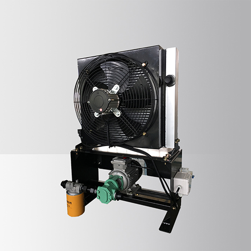
    Independent Oil Pump AC Axial Fan Heat Exchanger

    Oil Pump Ac Fan Cooling System

    Oil Pump Ac Fan Cooling System,Ac Fan Cooling System,Air Conditioner Cooling Fan,Aluminum Hydraulic Oil Cooler

    Xinxiang Zhenhua Radiator Co., Ltd. , https://www.thermictransfer.nl

    Previous Post: Common faults and repair schemes for mineral processing equipment classifiers
    Next Post: Purification of rare earth metals by electromigration - application examples
    Home
    Recent Posts
    • Sulfur ore beneficiation technology (4)
    • Metallurgical by-product gold extraction
    • Calcination method of Jatylo Neff arsenic gold o…
    • US Jinsishan Lithium Phosphate Concentrator
    • Estimation of the selection of 1000 tons of copp…
    • Production planning and development situation of…
    • Several problems caused by rotary kiln in the wo…
    • Unveiled the Traxon gearbox debuted by ZF in Chi…
    • Acid hydrolysis process of acid soluble titanium…
    • What is a detonating tube?
    • Recovery of bismuth, antimony and tungsten from …
    • Gold Extraction and Environmental Protection (4)
    • Practice of improving copper beneficiation index…
    • A pretreatment method for refractory metallurgic…
    • Common faults and repair schemes for mineral pro…
    • High efficiency concentrator
    • Purification of rare earth metals by electromigr…
    • Cost management concept
    • Xiaosigou copper-molybdenum ore selection plant
    • Fluorite flotation