
0 Preface
With the continuous development of the machinery manufacturing industry, precision machining has gradually become a major trend in modern manufacturing, and error compensation technology has thus developed rapidly. Error compensation includes hardware compensation and software compensation. The specificity of hardware compensation is relatively strong and has not been well developed at home and abroad. Software compensation is more versatile. Many scholars at home and abroad have studied it. Y. Y. Hsu and S. S. Wang et al. proposed a new 5-axis machine tool error compensation decoupling method, which calculates the error of the rotary axis and the moving axis of the machine tool respectively, and applies it to the post-processing of the machine tool to obtain an optimized NC program; Ibaraki et al. A new measurement method for the geometric error of the axis machine tool and error compensation was completed; Feng Huo et al. systematically studied the factors that influence the accuracy of contour milling machining, analyzed the compensation methods for various factors, and experimentally verified the feasibility of the compensation method. In China, He Zhenya studied the motion error compensation function of the PMAC card and realized the visual analysis and compensation of the spatial error of the machine tool using Matlab. Wang Wei et al. proposed a comprehensive error modeling method including geometric error and thermal error, and used the coordinate offset command of the numerical control system to perform real-time online compensation and achieved good results; Han Feifei et al. used machine tool geometric error analysis. Method, through the laser interferometer to detect each error of the machine tool, found the error regularity of each working axis and a certain axis in different working intervals, thereby improving the machining accuracy of the machine tool.
At present, most of the CNC machine tool space error compensation methods are difficult to integrate with the CNC system, simply mapping the error to the machining process, and the compensation effect is not ideal. Therefore, it is necessary to embed the spatial error compensation function into the numerical control system, realize the integration with the numerical control system, and improve its practicality, real-time and reliability.
This paper systematically studies the three-dimensional space error compensation method for CNC machine tools, focuses on the working principle of different compensation methods, and proposes an error compensation method based on the interpolation data of CNC system, which effectively improves the accuracy of CNC machine tools.
1. Three-dimensional geometric error compensation method for CNC machine tools
Common three-dimensional space error compensation methods for CNC machine tools are mainly the following.
1) NC code correction compensation method
Under the influence of CNC machine tool error, if the part is machined according to the ideal NC code, there is a machining error. In order to eliminate the influence of CNC machine tool error on the machining process, the NC code can be corrected and the corrected NC machining program can be used for the workpiece. Processes to compensate for CNC machine tool errors. The compensation flow chart is shown in Fig. 1. The NC code is input into the error compensation software, then the ideal tool path is generated, and the ideal tool path is corrected according to the error compensation prediction model to obtain the actual tool path trajectory, and finally the corrected tool path is generated. NC code. This method has a good effect on the compensation of geometric errors of CNC machine tools.
2) Interface type NC error compensation method
The interface type NC error compensation method is to add the error value calculated by the error prediction model to the interpolation process of the numerical control system. The basic working principle is as follows: Through a specific error compensation interface, the NC system passes the current machine tool parameters (machine position parameters, tool information, etc.) to the error prediction model, and calculates the corresponding error value through error prediction model to the NC system. The NC system processes the error value and generates a new NC program to compensate for the error. as shown in picture 2.
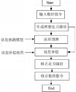
Figure 1 CNC machining instruction correction compensation diagram
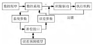
Figure 2 Interface type NC error compensation
Oil Equipment,Pumping Unit,Api Pumping Unit,Sucker Rod Pumping Unit
PUYANG RENHE INDUSTRY CO.,LTD , https://www.renhedownholetool.com