Motor Sizing Basics Part 4 - How to Calculate Radial Load and Axial Load
While selecting a motor, several key parameters such as load torque, acceleration torque, speed, and load inertia are typically taken into account. However, neglecting certain sizing parameters can significantly impact the performance and longevity of your machine. A motor's ability to handle various types of loads is crucial to ensuring optimal performance and durability.
Motors are designed with specific torque and speed specifications to ensure they meet the demands of the tasks they are assigned. However, their structural integrity is determined by their ability to withstand radial and axial loads. While torque and speed specifications tell us whether a motor can perform a task, the radial and axial load specifications tell us how long it can sustain that performance without failure.
The strength of a motor is derived from the combined rigidity of its casing, flange brackets, and output shaft assembly. For gear motors, the gears and additional bearings also contribute to this structural strength. However, the bearings closest to the load bear the brunt of this stress. As such, the radial and axial load specifications of a motor or gearhead are closely tied to the quality and design of its bearings.
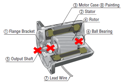
We’ve illustrated the internal structure of an AC motor and its gearhead below. The same principles of radial and axial load apply to all types of motors.
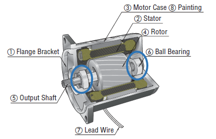 |
Starting from the inside, the rotor (4) and shaft (5) assembly are the only rotating parts of the motor, supported by ball bearings (6) at both ends. Surrounding the rotor, separated by a thin air gap, is the stator (2). The flange bracket (1) and the motor case (3) form the outer structure. Together, these components support all static and dynamic forces within the motor at its rated load. |
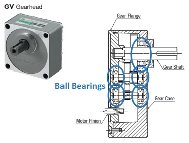 |
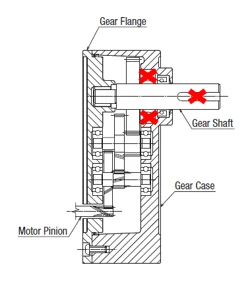
In a gearhead (or gearbox) attached to the motor’s pinion shaft, each toothed gear and output shaft is supported by its own bearing, while the input shaft (motor pinion) is still supported by the motor bearing. Notice that the bearing supporting the gear shaft (and load) is the largest. The gear flange and gear case complete the outer structure. The entire assembly supports all static and dynamic forces within the gearhead at its rated load. |
It's worth noting that the output shaft bearing in the gearhead is typically larger than the output shaft bearing in the motor, as the load on the gearhead shaft tends to be much greater than that on the motor shaft.
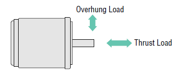
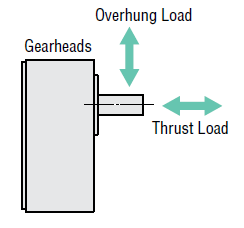
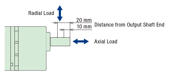
The images below illustrate both radial load (overhung load) and axial load (thrust load) forces acting on the shaft of a motor and a gearhead.
Â
| Radial Load (also known as Overhung Load) |
Radial Load refers to the maximum force that can be applied to the shaft in the radial direction (any direction perpendicular to the motor shaft axis). It is also called the "overhung load" because the load might appear to "hang" off the shaft. Radial loads vary depending on the distance between the installation point of the overhung load and its support bearing.Â
| Axial Load (also known as Thrust Load) |
Axial Load refers to the maximum force that can be applied to the shaft in the axial direction (parallel to or along the motor shaft axis). It is also referred to as the "thrust load" since thrust force and thrust load act along the same axis. A typical axial load is about half the motor weight, though this has increased over time.
These forces can act in any direction. For instance, if a motor has an axial load specification of 100 N, it means that the motor can support a 100 N load hanging from its shaft (if the shaft is facing down) or support a load on its shaft (if the shaft is facing up). 100 N (Newtons) is equivalent to about 10 kg.
| Why Are These Specifications Important? |
Both radial and axial load specifications are directly linked to the strength and mechanical rigidity of the bearings, shaft, and case assembly. Exceeding these specifications can result in damage to the ball bearings, such as flaking from the raceway and rolling elements, or even breaking the output shaft.
 |
 |
For example, if the permissible radial load is exceeded, the shaft might start bending and eventually break. If the permissible axial load is exceeded, the motor or gearhead bearing may deteriorate and eventually fail. In either case, the motor would cease operation or experience a reduced lifespan. The supporting element closest to the load is typically the first component to break.
|
TIP: Simple ball bearing test |
|
To check for internal damage of a motor or a gearhead, you can remove power and disassemble the motor from the gearhead, then manually rotate the shaft clockwise and counterclockwise. If the motor or gearhead is damaged, you would feel different resistance from one direction to another, hear abnormal noise, or not be able to rotate the shaft at all. |
How soon the life may end will depend on how much these specifications are exceeded and how long they remain so. For example, since our ball bearings are rated for 10,000 hours of life, exceeding either radial or axial load specifications by 10% could reduce its life by about 1,000 hours.
If you’re interested in a service life estimation based on bearing life, please contact our knowledgeable technical support engineers.
| How Are These Specifications Shown? |
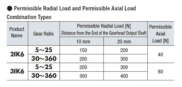
Manufacturers may display these specifications differently. Typically, a table (see example below) lists permissible radial loads and axial loads according to the gearhead size and the gear ratio. While the permissible axial load remains constant, the permissible radial load varies depending on the "distance from the end of the gearhead output shaft."
PS: This table lists permissible radial and axial loads only for common geared AC motors. When a chain, gear, belt, etc., is used as the transmission mechanism, the radial load is always applied on the gearhead shaft. For stepper motors, the permissible radial and axial loads for the motors are shown.
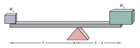
| The "Seesaw / Fulcrum" Effect (for Radial Load) |
In the above table, you can see that the radial load changes depending on the "distance from the end of the gearhead output shaft." This distance refers to the distance from the end of the load shaft to the point at which force is applied to the shaft (also the location of the installed load). The permissible radial load increases as the distance from the end of the shaft increases because this means the load is closer to the support bearing located just inside the gearhead flange. More load can be supported if the load is "hung" closer to the support bearing, which acts as the fulcrum in this case.
A "seesaw / fulcrum" is commonly used to explain this concept.
Â
Â
Static and Dynamic Radial and Axial Loads
Similar to dynamic and static moment loads, radial and axial loads also have both dynamic and static components. The table above is used to determine both.
For example, a static radial load includes the weight of the pulley and belt tension at rest. A dynamic radial load, which requires calculation, includes forces from the same pulley weight and belt tension while in motion. A static axial load would be the weight of the pulley if the motor shaft is in the vertical orientation. A dynamic axial load would be lower than the static axial load, so typically only the static axial load is considered. Make sure that the values are under the published values in the chart.Â
| TIP: Remember to include belt tension as radial force |
| Remember to size for belt tension! In my good old days as a technical support engineer, excessive belt tension was the cause of motor problems in many occasions. |
To ensure proper handling of all radial and axial loads, make sure these conditions are true:
- The static radial load is under the value in the chart.
- The dynamic radial load is under the value in the chart.
- The static axial load is under the value in the chart.
| The Equation For Dynamic Radial Loads |
For radial loads, there is an additional component of "dynamic" radial load, which is the radial load when in motion. Also make sure the calculated value is under the value in the chart (see above).
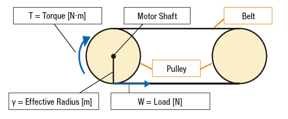
When pulleys, belts, gears, sprockets, chains, etc. are used as the transmission mechanism, the dynamic radial load is calculated with the following equation.
W = T / y
With a belt conveyor, the motor torque provides the driving force that generates work. This is shown as T, which is the amount of torque in N·m. If we consider y (effective radius in meters) to be the radius of the pulley, then we can calculate radial load or W (amount of work).
The actual equation is slightly more complex as load coefficient and service factor are considered.
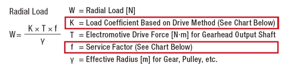
Other factors, such as drive method and load type, need to be considered for radial load. When using a flat belt drive method, for example, the radial load value increases.
As for service factor, which relates to operating conditions, factors such as frequent starting and stopping of the load as well as changing of rotation direction can affect the radial load.
Alright, let’s try a practical example.
| Example: Calculating radial load of a conveyor |
Consider the belt conveyor application example below. How would you calculate the value of required radial load that you’ll need from the motor?
Â
I’m working on a chain and toothed (sprocket) conveyor and using a 2IK6 motor with 360:1 gearhead. I need 10 N·m of torque on an 0.1-meter (effective) diameter sprocket. I’m guesstimating that the chain tension is about 10 N. I only intend to rotate in one direction. My sprocket is mounted 10 mm from the end of the shaft.
Can my gear motor handle the radial and axial load from my application?
Â
The first question I ask myself is: what equation do I use (we know this), and do I have all the variables?
Since we live in a perfect world, all the variables that are necessary for the calculation are laid out and provided in the preferred units. In reality, it usually takes more work. For example, notice that the load coefficient and the service factor were not given, but the drive method and type of load were given. Also, the values provided may be in different units, so an extra step of unit conversion may be needed.Â
Once again, we need to:
Make sure these conditions are true:
- The static radial load is under the value in the chart.
- The dynamic radial load is under the value in the chart.
- The static axial load is under the value in the chart.
| Static Radial Load = OK |
Static radial load would be belt tension. The 10 N was a guesstimate, but that’s the best information we have right now, so we’ll use it. At 10 mm from the end of the shaft, our maximum radial load for the 2IK6 motor is 200 N, so we’re good here.
| Dynamic Radial Load = OK |
Plug in values for every variable in the equation for dynamic radial load.
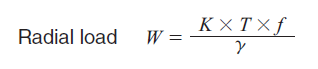
W = what we’re solving for in radial load in Newtons.
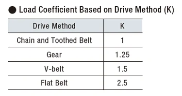
K = 1; chain and toothed belt conveyor
T = 10 N·m
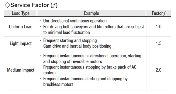
f = 1; uniform load / unidirectional continuous operation
y = effective radius of pulley = 0.1 meter (effective radius is where the belt contacts the pulley surface)
W = K x T x f / y
W = 1 x 10 x 1 / 0.1
W = 100 N
100 N is below the 200 N permissible radial load value, so we’re good here.
| Static Axial Load = OK |
Static axial load is actually unknown at this point, but looking at the application image, we should not have a lot of static axial load, and it definitely should be below the 40 N value in the chart, so we’re good here, too.
| Conclusion |
The 2IK6 motor with a 360:1 gear ratio gearhead will be able to handle both radial and axial loads.
Most motor sizing software does not consider axial or radial loads, so don’t forget to confirm your radial load and axial load after sizing your motor.
| Let Us Help! |
In most cases, a thorough motor sizing takes more work than you think. If your time is as valuable as we think it is, let our experts help!
To begin your motor sizing consultation with us, please use our  hbspt.cta._relativeUrls=true;hbspt.cta.load(2284573, '1726541c-dd49-4785-af36-f6786a53b911', {"useNewLoader":"true","region":"na1"}); , select one of the common applications (shown below), then fill in the blanks. A sizing report, including calculations, can be generated. Our knowledgeable technical support engineers are more than happy to analyze your motor sizing report with you to ensure you purchase the right motor the first time (we do not like RMAs either).
hbspt.cta._relativeUrls=true;hbspt.cta.load(2284573, '1845224e-9502-4f13-8c3b-2aa5c75abb0f', {"useNewLoader":"true","region":"na1"});
As I mentioned earlier, a successful motor sizing is only as good as the information provided. Users often oversize motors because either they don’t know the exact information necessary for sizing or they want to extend the life of the motor.
In the next post, I will provide some This is a small excavator weighing 800 kilograms. It has a small volume, flexible turning, and a width of less than 1 meter. It is the preferred tool for garden nurseries and is convenient to work with. Different front-end accessories can be added, such as different models of rakes, spiral conveyors, buckets, rakes, suitable for different work needs. Backhoe Loader is a fashionable specialized equipment that can be shifted to a certain extent by using specialized equipment such as excavators. With the emergence of hydraulic power attachments composed of tipping devices, crushers, grab buckets, or screw conveyors, backhoes are often used in many professional front-end Loader programs, especially for the upward thrust of small excavators. On many process websites, it is possible to see backhoe USR instead of mining, and websites with tilt rotator attachments are a powerful tool carrier. We are a true manufacturer looking for marketers worldwide. hbspt.cta._relativeUrls=true;hbspt.cta.load(2284573, '0db6848f-18ac-4888-89e7-bcacef169c20', {"useNewLoader":"true","region":"na1"}); . Here’s also a post explaining how to
0.8Ton Garden Digger,800Kg Hydraulic Crawler Excavators,800Kg New Mini Excavator,800Kg Mini Digger
Shandong Davoo Machinery Co., Ltd. , https://www.sddigger.com